Foresight Falcon User Manual
-
Introduction

Thank you for choosing the Foresight Sports Falcon. This guide will outline the safety requirements, installation process, setup, and troubleshooting guide for your Falcon. Should you need more assistance, please review the Falcon Product Support Page.
-
Safety Guidelines
Please read the following before use. Failure to follow the instructions could result in serious injury, property damage, and/or void the device warranty.
All installation work described in this guide should be performed by licensed contractors. Improper installation may result in personal injury, property damage, and void any product warranty. The installation work should be performed by at least two (2) qualified installers.
Falcon Ceiling Mount Precautions
The Falcon ceiling mount is designed specifically for mounting a Falcon to a ceiling or a Foresight Sports simulator frame. Do NOT attempt to mount additional items to the provided mount, as the additional weight may result in damage and/or failure.
Do NOT install the ceiling mount in a location where vibration or impact shock may occur. This may result in damage to or failure of the mount.
Prior to installing the Falcon ceiling mount, make sure the ceiling area is strong enough to hold a minimum of 75 pounds. If the ceiling area is not strong enough, reinforce the area prior to installation.
Never modify the ceiling mount, assembly components, or Falcon.
Do NOT install the ceiling mount and Falcon in a location where the operating temperature for the Falcon may be exceeded. Excessive temperatures may damage the Falcon. Recommended operating temperature range is 35F-115F.
Install the ceiling mount in a place free from excessive dust and humidity to prevent the lens or optical components of the Falcon from becoming clouded or dirty.
Do NOT use excessive force when adjusting the ceiling mount or Falcon.
-
Components
Falcon (x1)

Ceiling Mount (x1)

Height: 135mm (5.3in) Height: 11.5mm (.5in)
Length: 1110mm (43.7in) Length: 390mm (15.4in)
Width: 270mm (10.7in) Width: 148.5 (5.8in)
Weight: 11.8kg (27lbs) Weight: 400g (.9lbs)
Power Cord

Length – 6 feet
Ethernet Cable USB to USB-C


Calibration Wand

Fiducial Dispenser

Plastic Tee (x2)

NOTE: This installation package does not include lag screws for securing the ceiling mount to the ceiling. Selected installation screws must not exceed 6mm (.25”) diameter, washer recommended, must engage a ceiling joist by 25mm (1in), are capable of supporting a minimum of 75 pounds. If using drywall anchors they must be capable of supporting 22.68kg (50lbs) each for a total weight support of 100lbs (qty 4 anchors).
-
Features

-
Installation
Remove/Check Contents
Remove contents from the box. Make sure the box includes all components listed in this User Guide and that there are no damaged components. In addition, make sure the calibration wand has five white dots.
Installation Tips
Handle and install the power cord carefully. Incorrect installation may result in fire or electric shock. Observe the following precautions when installing:
Do not handle any electrical components with wet hands.
Do not use a power cord that appears to be damaged or modified.
Tighten all screws firmly after installation and final adjustment.
Do NOT use adhesives, lubricants, or oils to install and/or adjust the ceiling mount.
Do NOT loosen the screws after installation.
When performing electrical installation, make sure that no wiring comes into contact with mounting or assembly screws.
-
Installation Layout
It is important to check the layout of the simulator environment before installation. Ideally, the ceiling should be 9.5 to 10.5 feet tall, and the center of the hitting mat should be placed 10 to 12 feet from the screen and 4 feet away from the Falcon. There should be room to swing for both a left- and right-handed golfer.
The Figures below depict the ideal Falcon installation configuration.
MEASUREMENTS BELOW BASED ON CEILING MOUNT ONLY - IF USING SIM-IN-A-BOX BE SURE TO DEFER TO POSTED INSTRUCTIONS OR CONTACT SALES ASSOCIATE.


The Falcon has two hitting zones: the club zone and the ball only zone. The club zone collects data on both the ball and club at impact, the ball only zone collects ball data. Hitting zone dimensions for the club zone (dark blue) and ball only zone (light blue) are generally shown in the figure below.
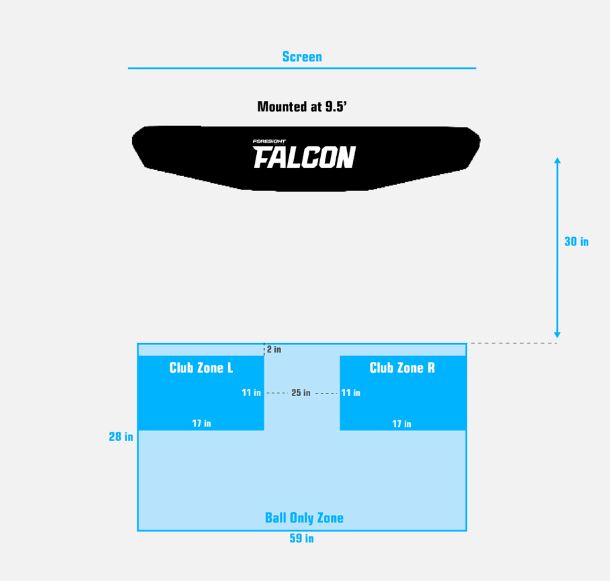
NOTICE: Hit Zone Size May Vary Slightly From Device To Device.
-
Installing Ceiling Mount
Locate ceiling joists or rafters.
Use recommended hardware to install the ceiling mount. Selected installation screws must not exceed 6mm (.25”) diameter, washer recommended, must engage a ceiling joist by 25mm (1in), are capable of supporting a minimum of 75 pounds. If using drywall anchors they must be capable of supporting 22.68kg (50lbs) each for a total weight support of 100lbs (qty 4 anchors).
Make sure screws can fit through the slots on the ceiling mount.
Screw the ceiling mount directly into ceiling joists or rafters with lag screws where possible. Use drywall anchors where joists or rafters are not available (see figure below). Must use a minimum of 4 screws.
Note: Hardware used to install the ceiling mount must support up to 75 pounds.


-
Mounting The Falcon
Use caution when mounting the Falcon. Two people are recommended for this operation. One person should be in place and stable on a ladder before the other person hands the Falcon up to them.
1) Identify the tabs on the ceiling mount that will engage with the Falcon.

2) Push the Falcon all the way into the mount bracket until the latch locks the device in place.
-
Connecting Data And Power Supply
1) Run/secure the ethernet cable from the location where the computer will be to the ceiling location where the Falcon will be mounted. Connect one end of the cable to the ethernet port on the Falcon (see figure below) and the other end to your network router or computer.
2) Run the power cord from a power source to the overhead location where the Falcon will be mounted. Plug one end of the power cord into the back of the Falcon (see figure below) and the other end into a GFCI-protected outlet.
Note: A direct Ethernet connection to the PC is recommended. If the Falcon is placed on a network, it is intended to be on a private and secure one.


-
Setup
-
Power On/Off and RESET
TO POWER ON:
To turn on the Falcon, press the POWER button to initiate boot of the Falcon. The grip end of a golf club can be used to reach the POWER button.

The status bar will illuminate yellow when the Falcon is turned on and booting up. The status bar will start blinking blue once the boot up is complete.
TO POWER OFF:
To turn off the Falcon, press the POWER button on the back of the device with the grip end of a golf club. The status bar should turn off completely.
TO RESET:
To reset the Falcon, hold the POWER button for 5 seconds.
Status Bar

-
-
Calibration
Foresight Calibration App
Please review the How-To: Falcon Calibration Walk Through video below before attempting calibration.
1) The Foresight Calibration App will be automatically installed on your computer with a new installation of FSX Play or FSX Pro and can be launched from the menu inside FSX game play. Ensure the Falcon is connected to your network router or PC through the Ethernet cable and the Falcon is powered on.
Note: If FSX Play and FSX Pro have been previously installed, you can download the stand-alone Foresight overhead device calibration software
-
Foresight Sports - Overhead Calibration Tool
Please see the Device User Manual & Calibration Video, to review the mounting and calibration process.
Release Date:
Once you have downloaded the stand-alone Foresight overhead device calibration software, you can launch the program and follow the instructions provided within the application or you can watch the help video shown above.
It is required that your PC is connected to the internet before starting calibration.
If you are unable to connect your Falcon to a PC with internet connection, you will need to reach out to your Foresight Sports support team to assist you with a manual calibration of your Falcon.
2) Launch the Foresight Calibration App from within FSX Play and follow the instructions.
The Foresight Calibration App will send data to the cloud, where a server will perform the required calibration computation*. The Falcon will reset itself during the process once it receives the calibration file from the server.
*Note: Your Falcon status bar will illuminate red during the calibration process. Your device is not in an error state, it is exchanging information with the Foresight Sports servers.
Once the Falcon resets and boots up, you should see a blue light appear on the Falcon - your calibration is complete!
-
-
Connecting To Software
Connect within FSX Play or FSX Pro
Connecting your Foresight Sports Falcon to our gaming and performance software is necessary to see your shot data. Once you have completed the overhead calibration process, launch either FSX Play or FSX Pro and navigate to the device connection screen. Your device will appear on screen once it’s recognized.
*Note: Serial number is underlined in blue on the image below.
Locate your device by serial number and click the connect button. You are now connected to software! If your device is not recognized, check your connection and click the refresh button to try again.

-
Troubleshooting
Falcon will not connect to software.
Is the Falcon connected correctly?
To check this, confirm the Ethernet cable is properly connected to the Falcon and to your computer.
Tip: If using any extension cable, be sure that it is connected correctly and, if needed, is using a hub that is powered.
Is the Falcon recognized and connected within the Software?
Locate the devices option and confirm your device is connected. If needed, reference the software user manual for guidance.
Falcon will not lock onto the ball.
Will your Falcon locate the ball in the hitting zone?
To confirm this, move the ball into the respective hitting zone and wait for the indicator light on the device to turn solid. If this does not happen, the view of the ball may be obstructed, or the hitting zone may not be identified correctly due to incorrect calibration.
Tip: Attempt to move the ball from the left and right hitting zones to diagnose if there is any change.
Falcon will not power on.
Is the Falcon receiving power?
Reset all connections. Remove the power cable from the back of the Falcon and then plug back in, check that the POWER button on the Falcon is illuminated blue, and check the connection to the wall outlet.
Foresight Calibration app error report.
If you have issues with Falcon calibration collect the log folder (all contents) and submit a support request for review.
Locate and collect the entire contents of the folder: C:\Users\[YOUR PC NAME]\AppData\LocalLow\ForesightSports\ForesightOverheadCalibration
Create a Support Request with the contents included. Use this link to create a support request: Contact Technical Support
Add details or an image of the error message you are seeing on the app, or the step and process where the app stopped working.
Submit the Report to the Support Team for review.
-
Product Compliance And Certifications
Regulatory Compliance
This section contains the following:
Safety Compliance
Electromagnetic Capability (EMC) and Wireless Compliance
Product Certification and Warning Notices
Safety Compliance
U.S. Nationally Recognized Testing Laboratory listing
UL 62368-1 3rd Edition Audio/Video, Information and Communication Technology Equipment – Part 1: Safety Requirements
Candian certification
CAN/CSA-C22.2 No. 62368-1-19 Audio/Video, Information and Communication Technology Equipment – Part 1: Safety Requirements
IEC Safety Compliance
- Reese’s Law Coin Cell Battery Warnings
- Immediately dispose of used batteries and keep away from children. Do NOT dispose of batteries in household trash.
- Even used batteries may cause severe injury or death.
- Call a local poison control center for treatment information.
- Battery can’t be removed and replaced.

IEC 62368-1:2018 Audio/video, information and communication technology equipment – Part 1: Safety Requirements
EU
Low Voltage Directive 2014/35/EU
EN 62368-1:2018 Audio/Video, Information and Communication Technology Equipment – Part 1: Safety Requirements
EMC and Wireless Compliance
U.S.
FCC 47 CFR Part 15, Subpart B – Verification Title 47: Telecommunication; Part 15 – Radio
Frequency Devices
This device complies with Part 15 of the FCC Rules. Operation is subject to the following
Two conditions: (1) This device may not cause harmful interference, and (2) This device
must accept any interference received, including interference that may cause undesired
Operation.
This equipment has been tested and found to comply with the limits for a Class B digital device, pursuant to part 15 of the FCC Rules. These limits are designed to provide reasonable protection against harmful interference in a residential installation. This equipment generates, uses and can radiate radio frequency energy and, if not installed and used in accordance with the instructions, may cause harmful interference to radio communications. However, there is no guarantee that interference will not occur in a particular installation. If this equipment does cause harmful interference to radio or television reception, which can be determined by turning the equipment off and on, the user is encouraged to try to correct the interference by one or more of the following measures:
Reorient or relocate the receiving antenna.
Increase the separation between the equipment and receiver.
Connect the equipment into an outlet on a circuit different from that to which the receiver is connected.
Consult the dealer or an experienced radio/TV technician for help.
Canada
ICES-003 Issue 7: 2020 Information Technology Equipment (including Digital Apparatus)
ISED Canada Compliance Statement
(English) Operation is subject to the following two conditions:
this device may not cause interference, andThis device must accept any interference, including interference that may cause undesired operation of the device.
(French) Son utilisation est soumise aux deux conditions suivantes:Cet appareil ne doit pas causer d’interférences et
il doit accepter toutes interférences reçues, y compris celles susceptibles d’avoir des effets indésirables sur son fonctionnement
English: for indoor use only
French: Pour usage intérieur seulementEuropean Union
EMC Directive 2014/30/EU
EN 55032:2015 Electromagnetic compatibility of multimedia equipment – Emission requirements
EN 61000-3-2:2014 Electromagnetic compatibility (EMC) - Part 3-2: Limit – Limit for harmonic current emissions (equipment input current ≤ 16 A per phase)
EN 61000-3-3:2013 Electromagnetic compatibility (EMC) - Part 3-3: Limits – L imitation of voltage changes, voltage fluctuations and flicker in public low-voltage supply systems, for equipment with rated current ≤ 16 A per phase and not subject to conditional
connection
EN 55035:2017 Electromagnetic compatibility of multimedia equipment; Immunity requirements
Radio Equipment Directive 2014/53/EU
ETSI EN 301 489-1 V2.2.3 (2019-11) Electromagnetic compatibility (EMC) standard for radio equipment and services; Part 1: Common technical requirements; Harmonised Standard for Electromagnetic Compatibility
ETSI EN 301 489-3 V2.3.2 (2023-01) ElectroMagnetic Compatibility (EMC) standard for radio equipment and services; Part 3: Specific conditions for Short- Range Devices (SRD) operating on frequencies between 9 kHz and 246 GHZ; Harmonised Standard for ElectroMagnetic Compatibility
ETSI EN 301 489-17 V3.2.4 (2020-09) ElectroMagnetic Compatibility (EMC) standard for radio equipment and services; Part 17: Specific conditions for Broadband Data Transmission Systems; Harmonised Standard for ElectoMagnetic Compatibility
Australia/New Zealand
AS/NZS CISPR 32:2015 Electromagnetic compatibility of multimedia equipment - Emission requirements
Japan
VCCI-CISPR32: 2016 Agreement of Voluntary Control Council for interference by Information Technology Equipment.
Korea
KS C 9832: 2023 Electromagnetic compatibility of multimedia equipment – Emissions requirements
KS C 9835: 2019 Electromagnetic compatibility of multimedia equipment: immunity requirements
KS X 3124:2020 Common electromagnetic compatibility test method for wireless devices
KS X 3125:2020 Electromagnetic compatibility test method for specific small power wireless devices
KS X 3126:2020 Specific low-power wireless devices for wireless data communication systems Electromagnetic compatibility test method
Taiwan
NCC Taiwan Warning Label:
(Mandarin Chinese) 取得審驗證明之低功率射頻器材,非經核准,公司、商號或使用者均不得擅自變更頻率、加大功率或變更原設 計之特性及功能。 低功率射頻器材之使用不得影響飛航安全及干擾合法通信;經發現有干擾現象時,應立即停用,並改善至無干 擾時方得繼續使用。前述合法通信,指依電信管理法規定作業之無線電通信。低功率射頻器材須忍受合法通信 或工業、科學及醫療用電波輻射性電機設備之干擾。應避免影響附近雷達系統之操作。 系統廠商應於平台上標示「本產品內含射頻模組: JODY-W2 字樣。
(English) Without permission granted by the NCC, any company, enterprise, or user is not allowed to change frequency, enhance transmitting power, or alter original characteristic as well as performance to an approved low power radio-frequency device.
The low power radio-frequency devices shall not influence aircraft security and interfere legal communications; If any interference is found or suspected, the user shall immediately cease operating the equipment until the interference has been prevented. The said legal communications means radio communications is operated in compliance with the Telecommunications Act. The low power radio-frequency devices must be susceptible with the interference from legal communications or ISM radio wave radiated devices.

Thailand
EN 62311:2008 Assessment of electronic and electrical equipment related to human exposure restrictions for electromagnetic fields (0 Hz – 300 GHz)
Singapore
IMDA Device Registration:
Complies with
IMDA Standards DA105282
Product Certifications and Warning Notices
Marks of Compliance

